The Scale HC3 Advantage

For years I have been pitching ideas about how a performant, highly reliable architecture for the small and medium business market should be approached.  Concepts like maintaining high reliability across all layers of the architecture, reducing the total number of points of failure whenever possible, reducing complexity, leveraging mirroring instead of parity for storage, keeping storage close to compute and so forth.

What I like about the Scale HC3 approach to hyperconvergence is that it addresses all of these items and more.  Scale takes all of the components of a complete platform and reduces them into a singular “package” that is deployed to all nodes in the system making every layer of the system as redundant as all of the other layers.  Even the management console itself is automatically replicated and available from every node in the cluster,  independently!

Compute and storage are integrated into the same package sitting together on each node.  This allows for the lowest latency in communications and the highest reliability both per node, as there is less to fail by way of having fewer moving parts, and also across the entire architecture by making each stable building block replicated so that nothing depends on any single node for computer, storage, management or orchestration.

Instead of the “traditional” approach so often associated with virtualization, where several layers of services are separate yet totally dependent upon each other, the Scale hyperconverged approach flattens these taking us to the opposite end of the spectrum from the infamous “inverted pyramid of doom” to a flat, broad “brick”.  No single points of failure, no highly fragile components.  Keep each component reliable on its own, then make them redundant anyway.

Digging down to the storage layer, the Scale HC3 uses a RAIN approach which can most easily be described as a “network RAID 1e” design.  RAID 1e is an interesting twist on RAID 10 which basically adds a striping mechanism inside the mirrors so that you never have anything but mirroring but the mirrors are not at the disk level but at the block level and spread out among many disks.  RAID 1e is more advanced and more flexible than RAID 10 and brings some minor performance and reliability advantages but, more importantly, allows a RAID 10 approach to be used effectively over a network without having to resort to the fragility of RAID 01.  Scale does not use actual RAID, but true RAIN, that does intelligent block mirroring in the cluster with logic not only about drives, not about nodes on which the drives sit.  We only use RAID as an example for comparison.

The Scale HC3 also adds powerful hybrid spinning disk and solid state drive tiering using a heat map approach to determining which blocks are being used regularly and which are predominantly idle.  This allows the system to intelligently move blocks from slow spinning storage to high performance SSD for performance without needing all storage to sit on SSDs.  This keeps cost down while also allowing for large capacity.  The heat map approach, coupled with a simplistic priority management system, makes this nearly transparent to end users.

Scale also takes the management of a complicated beast like a full virtualization stack and makes it simple and easy for a small business IT department to manage.  SMB IT departments are very busy places being pulled in a lot of simultaneous directions.  It is very important that their solutions, especially the critical ones on which the most depends, are elegant, well supported, effective and easy to manage.  Scale provides a solution that allows for growth, performance and high reliability while maintaining an astonishing degree of ease of use. Even an IT department with all of the resources and experience to manage the most complex and demanding infrastructure can benefit by not wasting time where there is no competitive advantage and, instead, putting their efforts to use where they can most benefit the business.

The Scale HC3 allows small and medium business IT departments to stop worrying about how to design a system to meet their needs, and instead focus on the what’s most important to their business and what provides them a unique, competitive advantage.


[Commissioned for the Scale Blog]
Leveraging Microsoft RDS on Scale HC3

One of the great advantages of a centralized and unified infrastructure platform like the Scale HC3 is the ability to use the platform to provide centralized desktop and end user services along side traditional server services.  The high speed back plane allows server and desktop resources to communicate at high speeds and the centralized management lowers the total cost of ownership often associated with these types of services.  Applications like file serving and latency sensitive communications particularly benefit from the architecture.

For the majority of businesses, the approach that will make the most sense to add remote end user computing services to their environment will be through the use of Microsoft’s own Remote Desktop Servers or RDS, as most environments seek to provide an experience similar to  a traditional Windows desktop.  Microsoft’s RDS is a powerful toolset and relatively easy to implement.  It is a great starting point for offering a range of services.

Because of the high availability nature of the Scale HC3 platform we have good choices as to how to approach planning and provisioning an RDS deployment.  We can choose to keep our deployment small and simple and utilize the Scale HC3 cluster’s built in high availability features to maintain our environment through hardware failure or we can leverage high availability from the RDS environment for this.

In a small deployment, it would be most common to leverage the Scale HC3’s high availability features to maintain the availability of our RDS services.  Doing this allows us to run a single RDS instance with a minimum of licensing, resource and maintenance overhead.  This is the simplest approach and is very effective.  This is an excellent way for the majority of customers to make the best use of the Scale HC3 platform.  Scale can do the heavy lifting in this case and we are able to focus our efforts in places where they are more effective.

In large deployments having a single RDS instance may not be adequate.  At this point it would generally become reasonable to move to a multi-server RDS deployment with workloads load balanced across the instances.  Typically we would want to see no more than a single RDS server deployed per Scale HC3 node to best leverage the available resources.  In this way as many RDS server instances could be deployed as needed to handle the environmental capacity.

In most cases, even with the larger deployment across many nodes, we would use load balancing in front of the RDS farm, but we would still use the Scale HC3 cluster’s built in high availability features to handle hardware failures by moving running workloads from a failed node to an available node.  The load balancer would see the same instance with the same IP address allowing for a nearly transparent recovery that is fully automated and requiring a minimal of effort.

In more extreme cases where the full capacity of the cluster is required it is possible to configure one RDS instance per physical cluster node and to disable high availability features and instead utilize the load balancing functions to shift load to remaining nodes.  This would result in a graceful loss of performance rather than an outage.  Unless resources were extremely constrained already, user allocated CPU and memory would decline but system functionality would remain.  This is not as ideal a full high availability solution but can be a very functional alternative to the cost of hardware for that level of protection.

Microsoft Windows RDS and Scale make an obvious partnership.  Scale focuses on making the platform as easy and robust as possible while Microsoft’s Windows and RDS product provide us the simplest entry point into the shared computing space.  For small and medium businesses and especially for on premises deployments RDS is often the perfect choice for moving to centralized, thin client-based computing and can be a key enabler for workforce mobility, security and even bring your own device options.

[This piece was commissioned for the Scale Blog.]


Logical Volume Managers

A commonly used but often overlooked or misunderstood storage tool is the Logical Volume Manager.  Logical Volume Managers, or LVMs, are a storage abstraction, encapsulation and virtualization technology used to provide a level of flexibility often otherwise unavailable.

Most commonly an LVM is used to replace traditional partitioning systems, and sometimes additional functionality is rolled into an LVM such as RAID functions.  Nearly all operating systems offer an integrated LVM product today and most have for a very long time.  LVMs have become a standard feature of both server and client side storage management.

LVMs do not necessarily offer uniform features but common features often included in an LVM are logical volumes (soft partitioning), thin provisioning, flexible physical location allocation, encryption, simple RAID functionality (commonly only mirror based RAID) and snapshots.  Essentially all LVMs offer logical volumes, snapshots and flexible allocation; these being considered fundamental LVM functions.

Popular LVMs include Logical Disk Management on Windows Server 2000 through Server 2008 R2, Storage Spaces on Windows 2012 and later, LVM on Linux, BtrFS on Linux, Core Storage on Mac OSX, Solaris Volume Manager on Solaris, ZFS on Solaris and FreeBSD, Vinum Volume Manager on FreeBSD, Veritas Volume Manager for most UNIX systems, LVM on AIX and many more.  LVMs have been increasingly popular and standard since the late 1980s.  ZFS and BtrFS are interesting as they are filesystems that implement an LVM inside of the filesystem as an integrated system.

An LVM consumes block devices (drive appearances) and creates logical volumes (often referred to as LVs) which are themselves drive appearances as well.  Because of this, an LVM can sit at any of many different places in the storage stack.  Most commonly we would expect an LVM to consume a RAID array, split one RAID array into one or more logical volumes with each logical volume having a filesystem applied to it.  But it is completely possible for an LVM to sit directly on physical storage without RAID, and it is very possible for RAID to be implemented via software on top of the logical volumes rather than beneath them.  LVMs are also very useful for combining many different storage systems into one such as combining many physical devices and/or RAID arrays into a single, abstracted entity that can then be split up into logical volumes (with single volumes potentially utilizing many different underlying storage devices.)  One standard use of an LVM is to combine many SAN LUNs (potentially from a single SAN system or potentially from several different ones) into a single volume group.

While LVMs provide power and flexibility for working with multiple storage devices and types of storage devices while presenting a standard interface to higher layers in the storage stack, probably the most common usages are to provide for flexibility where rigid partitions used to be and for snapshots.  Traditional partitions are rigid and cannot be resized.  Logical volumes can almost always be grown or shrunk as needed making them tremendously more flexible.

Snapshots have become a major focus of LVM usage in the last decade, although mostly this has happened because of snapshot awareness growing rather than a recent shift in availability.  Commodity virtualization systems have brought snapshots from an underlying, storage industry knowledge component into the IT mainstream.  Much of how virtualization technologies tend to tackle storage virtualization can be thought of as being related to LVMs, but generally this is similar functionality offered in a different manner or simply passing LVM functionality on from a lower layer.

Today you can expect to find LVMs in use nearly everywhere, even implemented transparently on storage arrays (such as SAN equipment) to provide more flexible provisioning.  They are not just standardly available, but standardly implemented and have done much to improve the reliability and capability of modern storage.

Drive Appearance

One of the more common, yet more tricky fundamental concepts in computing today is the concept of drive appearance or, in other words, something that appears to be a hard drive.  This may sound simple, and mostly it is, but it can be tricky.

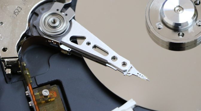
First, what is a hard drive.  This should be simple.  We normally mean a traditional spinning disk Winchester device such have been made for decades in standard three and a half inch as well as two and a half inch form factors.  They contain platters that spin, a drive head that moves forward and backward and they connect using something like ATA or SCSI connectors.  Most of us can pick up a hard drive with our hands and be certain that we have a hard drive.  This is what we call the physical manifestation of the drive.

To the computer, though, it does not see the casing of the drive nor the connectors.  The computer has to look through its electronics and “see” the drive digitally.  This is very, very different from how humans view the physical drive.  To the computer, a hard drive appears as an ATA, SCSI or Fibre Channel device at the most basic physical level and are generally abstracted at a higher level as a block device.  This is what we would call a logical appearance, rather than a physical one.  For our purposes here, we will think of all of these drive interfaces as being block devices.  They do differ, but only slightly and not consequentially to the discussion.  What is important is that there is a standard interface or set of closely related interfaces that are seen by the computer as being a hard drive.

Another way to think of the logical drive appearance here is that anything that looks like a hard drive to the computer is something on which the computer format with a filesystem.  Filesystems are not drives themselves, but require a drive on which to be placed.

The concept of the interface is the most important one here.  To the computer, it is “anything that implements a hard drive interface” that is truly seen as being a hard drive.  This is both a simple as well as a powerful concept.

It is because of the use of a standard interface that we were able to take flash memory, attach it to a disk controller that would present it over a standard protocol (both SATA and SAS implementations of ATA and SCSI are common for this today) and create SSDs that look and act exactly like traditional Winchester drives to the computer yet have nothing physically in common with them.  They may or may not come in a familiar physical form factor, but they definitely lack platters and a drive head.  Looking at the workings of a traditional hard drive and a modern SSD we would not guess that they share a purpose.

This concept applies to many devices.  Obviously SD cards and USB memory sticks work in the same way.  But importantly, this is how partitions on top of hard drives work.  The partitioning system uses the concept of drive impression interface on one side to be able to be applied to a device, and on the other side it presents a drive impression interface to whatever wants to use it; normally a filesystem.  This idea of something that using the drive impression interface on both sides is very important.  By doing this, we get a uniform and universal building block system for making complex storage systems!

We see this concept of “drive in; drive out” in many cases.  Probably the best know is RAID.  A RAID system takes an array of hard drives, applies one of a number of algorithms to make the drives act as a team, and then present them as a single drive impression to the next system up the “stack.”  This encapsulation is what gives RAID its power: systems further up the stack looking at a RAID array see literally a hard drive.  They do not see the array of drives, they do not know what is below the RAID.  They just see the resulting drive(s) that the RAID system present.

Because a RAID system takes an arbitrary number of drives and presents them as a standard drive we have the theoretical ability to layer RAID as many times as we want.  Of course this would be extremely impractical to do to any great degree.  But it is through this concept that nested RAID arrays are possible.   For example, if we had many physical hard drives split into pairs and each pair in a RAID 1 array.  Each of those resulting arrays gets presented as a single drive.  Each of those resulting logical drives can be combined into another RAID array, such as RAID 0.  Doing this is how RAID 10 is built.  Going further we could take a number of RAID 10 arrays, present them all to another RAID system that puts them in RAID 0 again and get RAID 100 and so forth indefinitely.

Similarly the logical volume layer uses the same kind of encapsulation as RAID to work its magic.  Logical Volume Managers, such as LVM on Linux and Dynamic Disks on Windows, sit on top of logical disks and provide a layer where you can do powerful management such as flexibly expanding devices or enabling snapshots, and then present logical disks (aka drive impression interface) to the next layer of the stack.

Because of the uniform nature of drive impressions the stack can happen in any order.  A logical volume manager can sit on top of RAID, or RAID can sit on top of a logical volume manager and of course you can skip or the other or both!

The concept of drive impressions or logical hard drives is powerful in its simplicity and allows us great potential for customizing storage systems however we need to make them.

Of course there are other uses of the logical drive concept as well.  One of the most popular and least understood is that of a SAN.  A SAN is nothing more than a device that takes one or more physical disks and presents them as logical drives (this presentation of a logical drive from a SAN is called a LUN) over the network.  This is, quite literally, all that a SAN is.  Most SANs will incorporate a RAID layer and likely a logical volume manager layer before presenting the final LUNs, or disk impressions, to the network, but that is not required to be a SAN.

This means, of course, that multiple SAN LUNs can be combined in a single RAID or controlled via a logical volume layer.  And of course it means that a SAN LUN, a physical hard drive, a RAID array, a logical volume, a partition…. can all be formatted with a filesystem as they are all different means of achieving the same result.  They all behave identically.  They all share the drive appearance interface.

To give a real world example of how you would often see all of these parts come together we will examine one of the most common “storage stacks” that you will find in the enterprise space.  Of course there are many ways to build a storage stack so do not be surprised if yours is different.  At the bottom of the stack is nearly always physical hard drives, which could include solid state drives.  This are located physically within a SAN.  Before leaving the SAN the stack will likely include the actual storage layer of the drives, then a RAID layer combining those drives into a single entity.  Then a logical volume layer to allow for features like growth and snapshots.  Then there is the physical demarcation between the SAN and the server which is presented as the LUN.  The LUN then has a logical volume manager applies to it on the server / operating system side of the demarcation point.  Then on top of that LUN is a filesystem which is our final step as the filesystem does not continue to present a drive appearance interface but a file interface, instead.

Understanding drive appearance, or logical drives, and how these allows components to interface with each other to build complex storage subsystems is a critical building block to IT understanding and is widely applicable to a large number of IT activities.

The Information Technology Resource for Small Business